Every Utility Network’s Conflation process has intricate business rules. Assets / structures always have a geometric and spatial relationship with their respective linear network. In the real world scenario, we will have instances where the network alignment and relative spatial positions will be different at different locations. Shift between linear network and the assets / structures are not uniform and heterogeneous. There is an industry challenge to incorporate relational assets conflation into the architecture of custom conflation. This plays a key role in providing business solutions across the enterprise.
“Similar is not the same”
Post Conflation of Linear network using Auto Generated Ground Control Points (GCPs), challenge lies in conflating the assets / structures to align to the Conflated Linear Utility Networks. Regular conflation of assets / structures is possible through the GCP’s using a universal mathematical transformation algorithm. But due to the industry specific business rules, there arises a need to transform the assets / structures with precision and also in relation to Linear Networks.
RMSI customized conflation follows three basic principles:
- Generation of Real World Native Platform Symbology
(This gives the Visual Look & Feel of the Native Environment)
- Spatial Relationship Builder with Linear Network.
(The Relational Manager that tracks the Positions, Alignment, Directions)
- Magnet concept (RMSI USP) for assets / structures (Direct & Interlinked Subtype).
Symbology Generation: Utilities across the globe use various formats for their GIS requirements. Conflation Service providers may not always necessarily have time to reproduce the tools in all the platforms. While that should not be a showstopper, they should have the means to be able to import / export from native format to their standard format.
Every native geospatial data when displayed has intricate characteristics that need to be replicated across the entire lifecycle of the project. Cartographic Rules across various Geospatial Native Platforms also vary from vendor to vendor. A rotation angle in Autodesk might work in radians whereas the rotation angle in ESRI might work in degrees and few customized spatial datasets have a base angle defined and angles defined across the vertical (Left / Right) (Top / Bottom)
XML based export / import methods along with in-depth knowledge on the object behavior techniques give the dataset an intelligent visual look. Symbology generation immensely helps Whitespace Management, Cartographic Display to better understand the data & the relations with respect to the Linear Network.
Points are sub classified based on their attributes into Symbols / Text / Multi Text along with few other parameters of Symbol Rotation / Text Height / Text Font / Justification / Orientation.
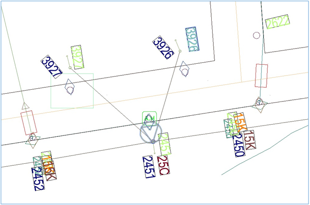
Example: Symbology Generated from Small World Model into the Autodesk Environment
Spatial Relationship Builder
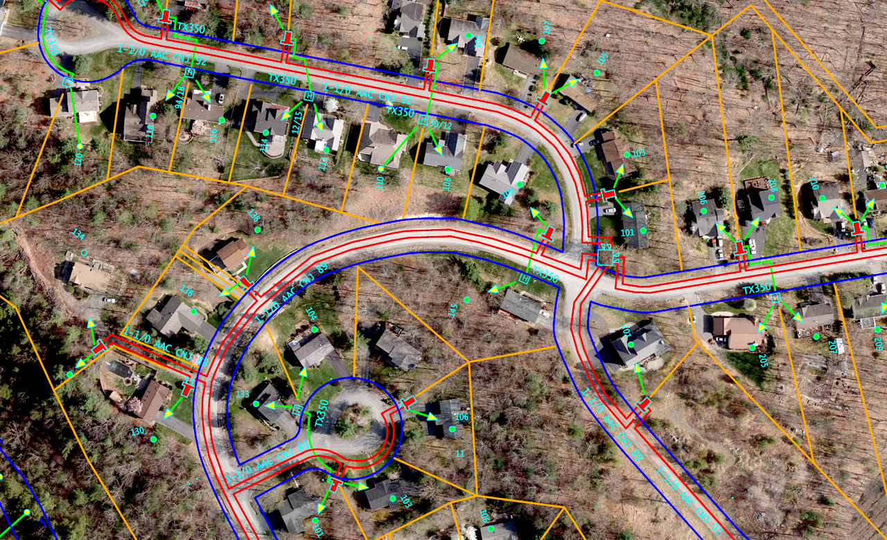
During pre-processing stage, every asset / structure relationship is maintained to its nearest Linear Geometry. Network can have a specific rule based filter to leverage the algorithm to build relationships on a project based specific requirement.
For Example, utility assets / structures need not have relationship build with Street Center Lines. They can relate to Network Linear Features such as transmission / distribution lines
ConflateX stores every low level detail of the dataset in the object geometry during preprocessing stage and this data store is used for Feature Mapping and Manipulation
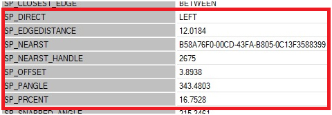
The above indicates the Symbol is to the LEFT of the Linear Network with in ‘SP_NEARST’ B58A76F0-00CD-43FA-B805-0C13F3588399 and inclined @ 343 degrees with an offset of 3.8938 and is @ 16.7528 % percent distance from the Nearest Linear Object with B58A76F0-00CD-43FA-B805-0C13F3588399
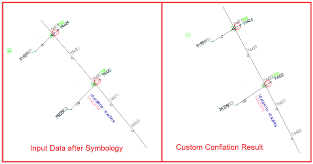
Magnet Concept:
After the Linear Network is conflated using the traditional algorithms, this magnet functionality adjusts the symbols. From the above example, magnet function identifies the nearest object with the ID and moves the symbol precisely at an offset of 3.8938. This approach is far more desirable and scalable to even the Subtype Matches (Bunch). In utility Conflation, few symbols move in PAIRs and maintain uniform distance across the life cycle with an anchor point. Below are the advantages of magnet concept.
- Synchronous Conflation of Features (assets / facilities / structures)
- Quick TAT & Bunch Concept
- Zero User Intervention
- Higher Success rate of Auto Conflation Percentage with Relation Builder
Conclusion: Geospatial Vector Conflation is not merely applying a uniform transformation across the GCP’s. For critical Conflation needs a low level understanding of the rule base and subsequent improvisations are definitely essential to get the desired accuracy levels.
With a configurable model embedded in ConflateX the relation based accessory movements are taken care with proven results of higher accuracies across the complete lifecycle of vector conflation.